Making a macro pad from scratch
I designed and built a QMK/VIAL macro pad from scratch. Let me tell you about the things I learned and useful resources I found as a beginner.

In August 2022, I made a password button using a mechanical switch and an Arduino. Now, I’ve finally taken the next step and made a macro pad - and my first-ever PCB!
This post is an update about one of the projects I’ll be pursuing this year. I think macro pads are cool desktop accessories and making one can be a fun project for you too.
In case you want to make one yourself, I prepared a step-by-step guide for creating a parametric model of the enclosure on Fusion 360. I also wanted to share some of the resources I found useful for learning about macro pads and mechanical keyboards, firmware, and using Autodesk Eagle to design a PCB.
Contents
- What is a Macro Pad?
- Why make one?
- The concept
- Prototyping
4.1. 3D printing
4.2. Wiring - Keyboard firmware
5.1. Arduino
5.2 QMK
5.3 VIAL - Making a PCB
- The finished prototype
- Keycaps
- Next Steps
What is a Macro Pad?
Macro pads are keyboards with a small number of keys. They can be configured to do different kinds of things and simplify workflows, gaming or media control on a computer. For instance, some keys could do a sequence of things when pressed, like simulating a combination of keys, opening a program, running a script, and so on.
As with mechanical keyboards, macro pads offer infinite possibilities for customization, and there is a growing online community of DIYers, collectors, and enthusiasts around them. The main places to find information about them are GeekHack, and Reddit, but there are also other websites out there, and tons of Discord servers.
Why make one?
A macro pad is a perfect challenge
Complex enough that I have to put some effort into making one. Easy enough that I don’t get frustrated. It’s a fun hobby! Also, I wanted to challenge myself into making a PCB.
Improving workflow and productivity
I thought I could configure the macro pad to run different key combinations depending on what I’m doing: if working on Visual Studio Code, I could run editing actions with a single button. Or when I’m working on a CAD model, I could do modeling operations or run scripts to improve my workflow.
Other reasons
I miss working on product design projects outside of the Automotive world.
A custom-made macro pad could even be a nice gift for friends and family, and if there's interest, it might even turn into a commercial product, or at least give me the inspiration to build other things.
The concept
There are several designs online for 3x3 macro pads, but I wanted to make one from scratch to learn as much as possible. Because why not?
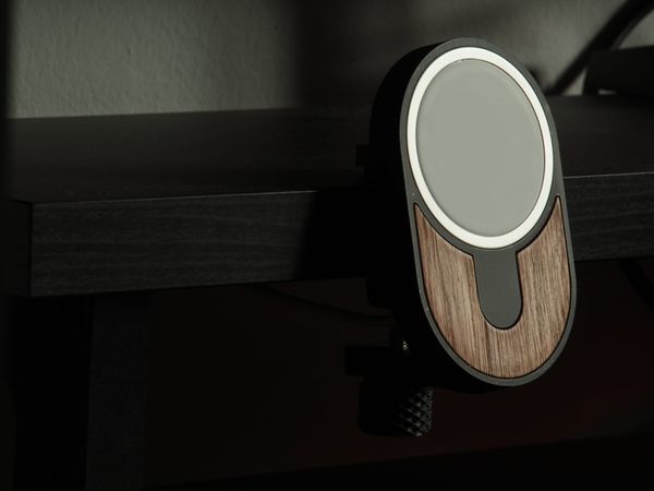
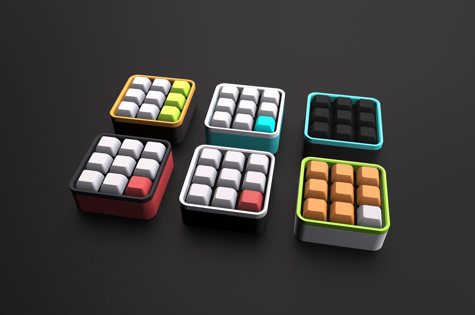
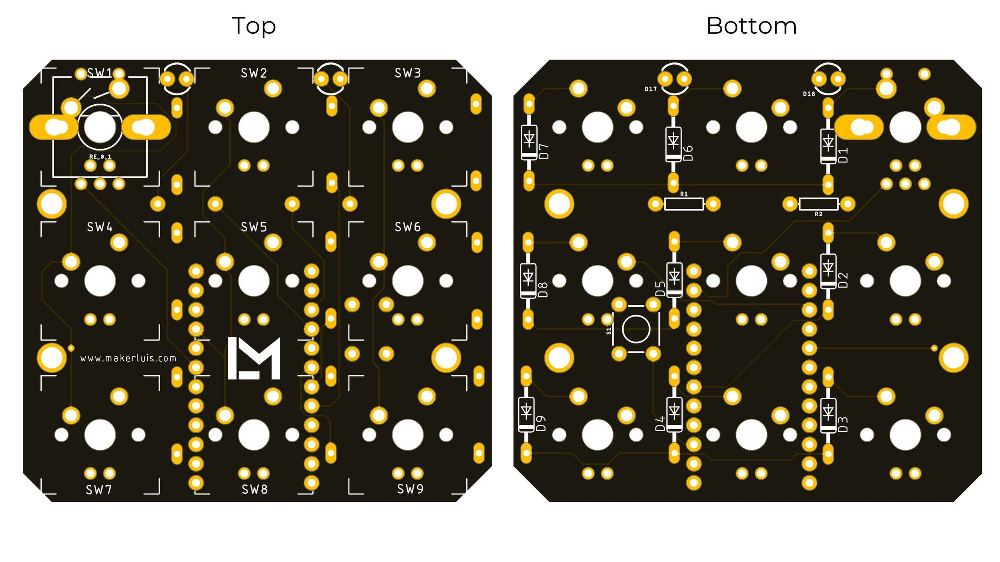
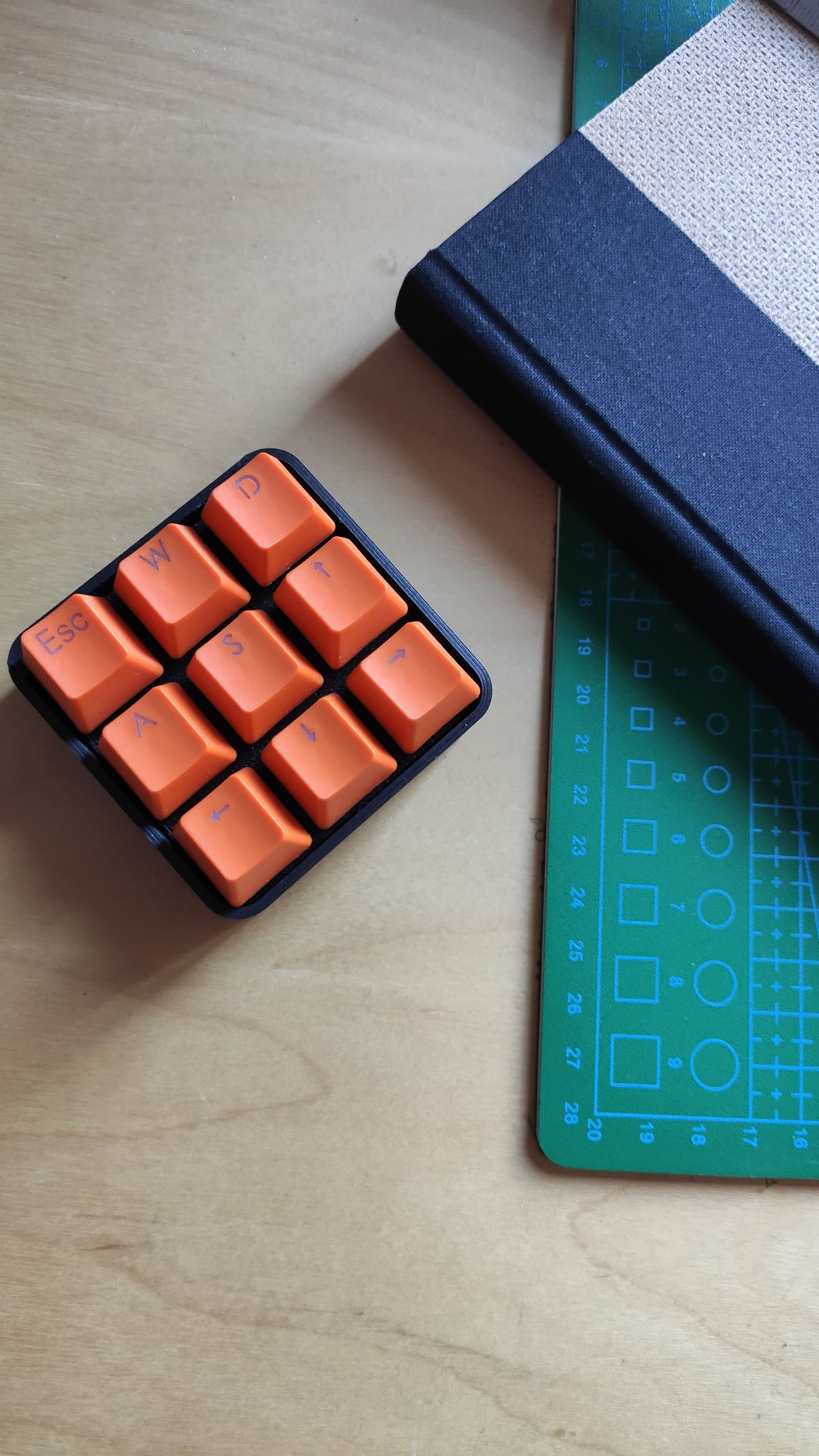
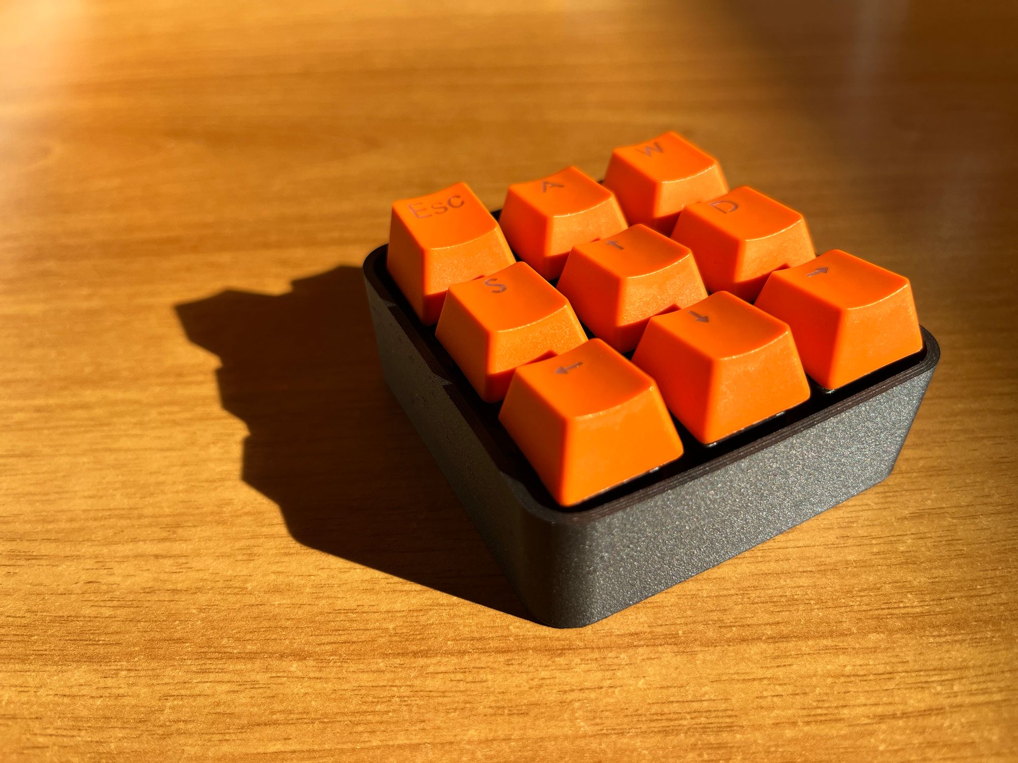
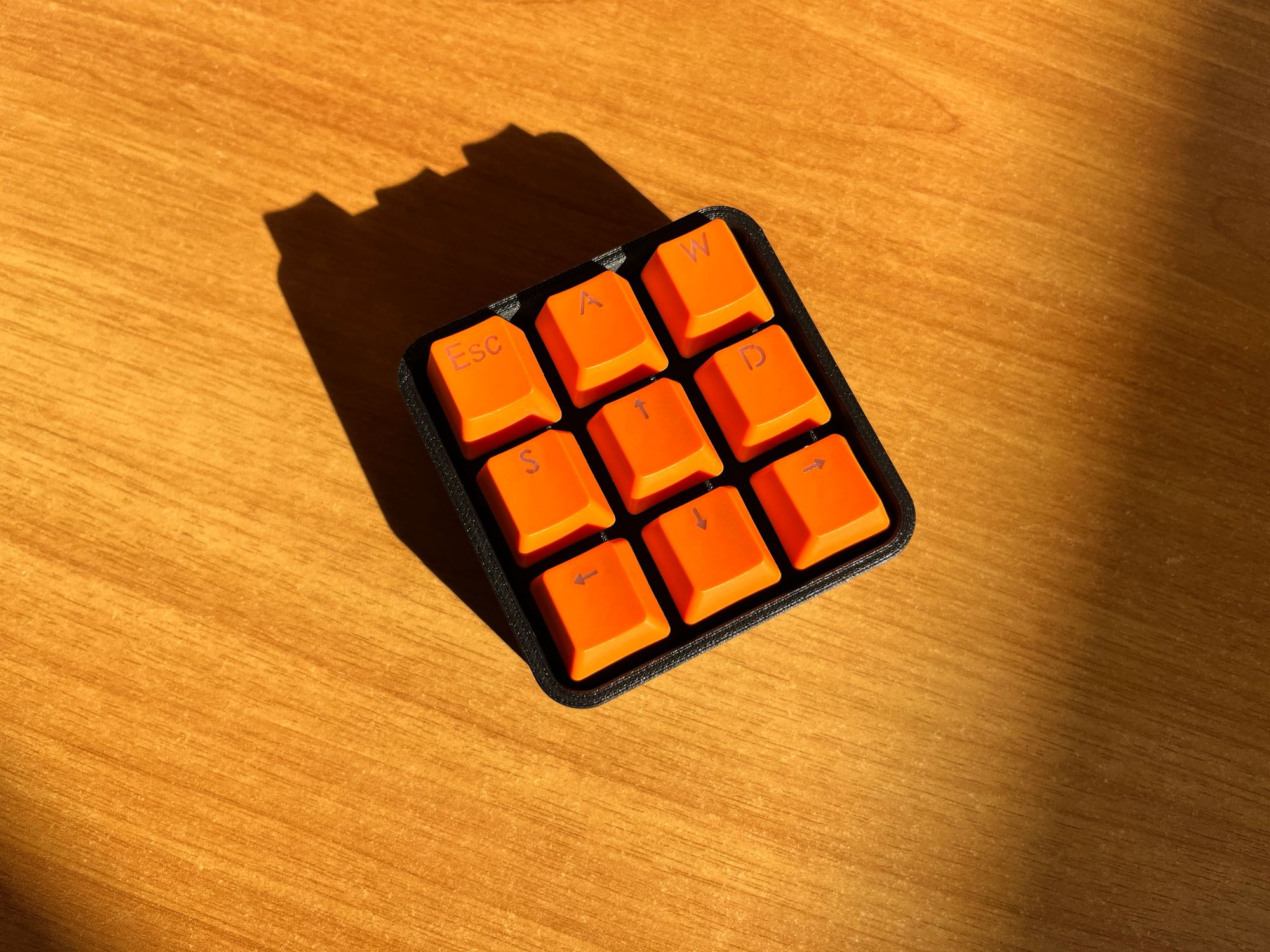
The latest version at the time of writing this post looks like the figures below. I named it Core_00.
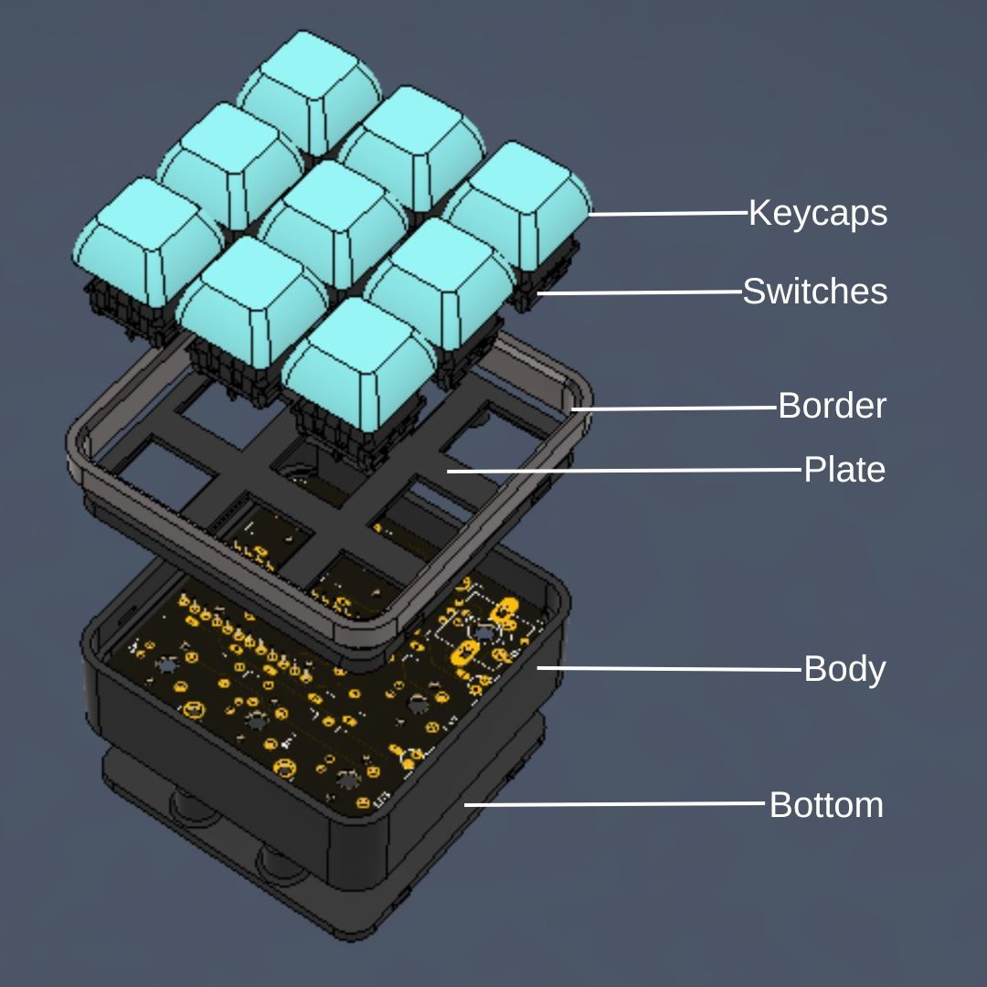
Designing a case was pretty straightforward, at least to get a working prototype. You can see all the steps I followed to create the first version of the case in the guide I made.
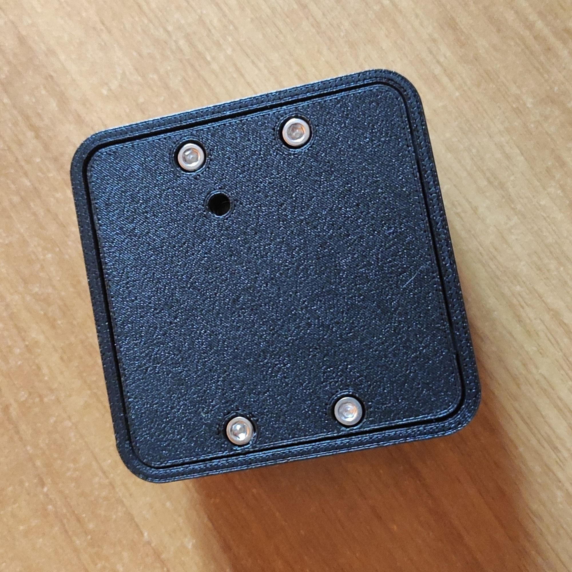
For the first working version, I made a unibody enclosure, using 3D printed features to snap the switch plate into place. When I moved to the PCB design, I included M3 threaded brass inserts.
Having a parametric model is useful to make changes to the design when switching from a hand-wired circuit to a PCB. It just requires editing some parameters to adjust the spacing of the switches and the height of the body, and adding some additional features.
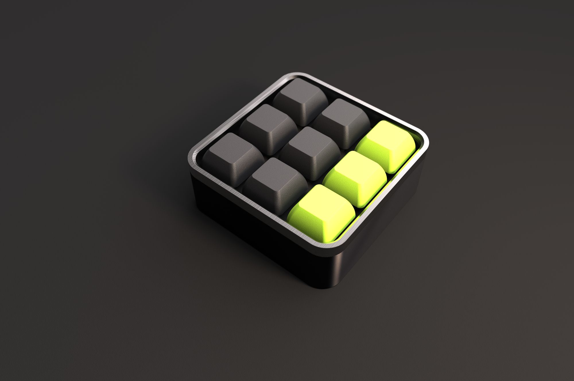
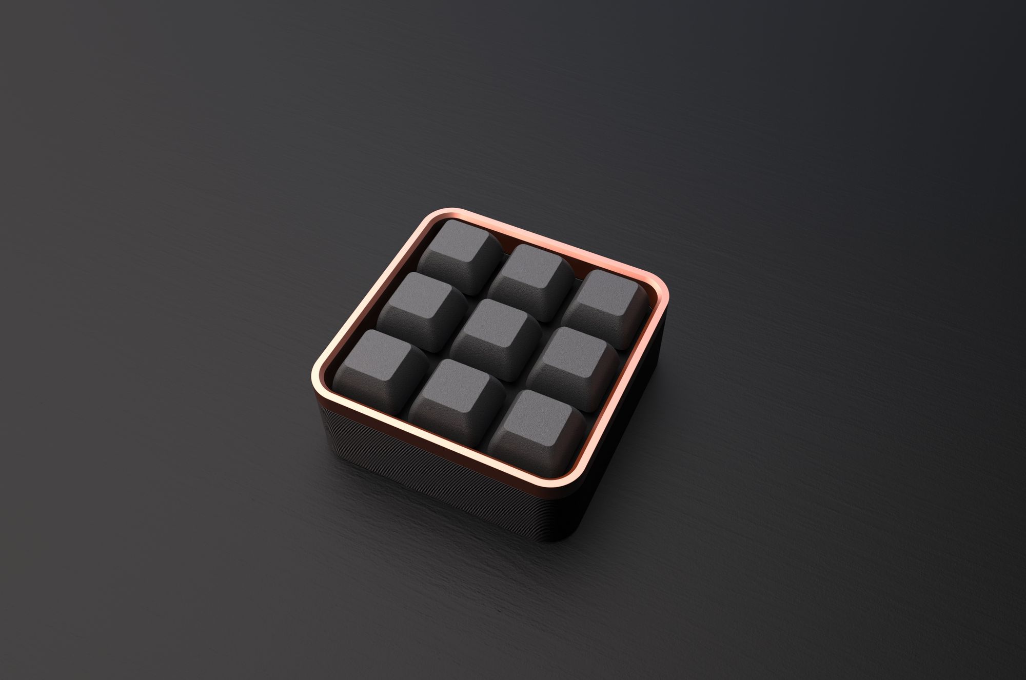
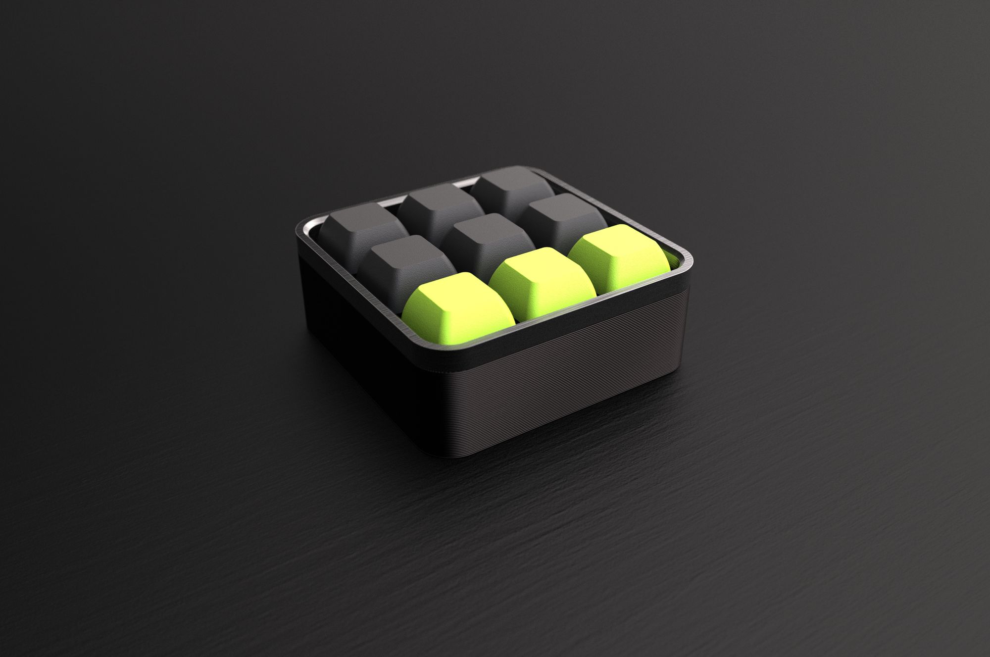
The Core_00 is a modular design. The prototypes are 3D printed, but my goal is that some of the components can be made out of metal, wood, or non-3D-printed plastic.
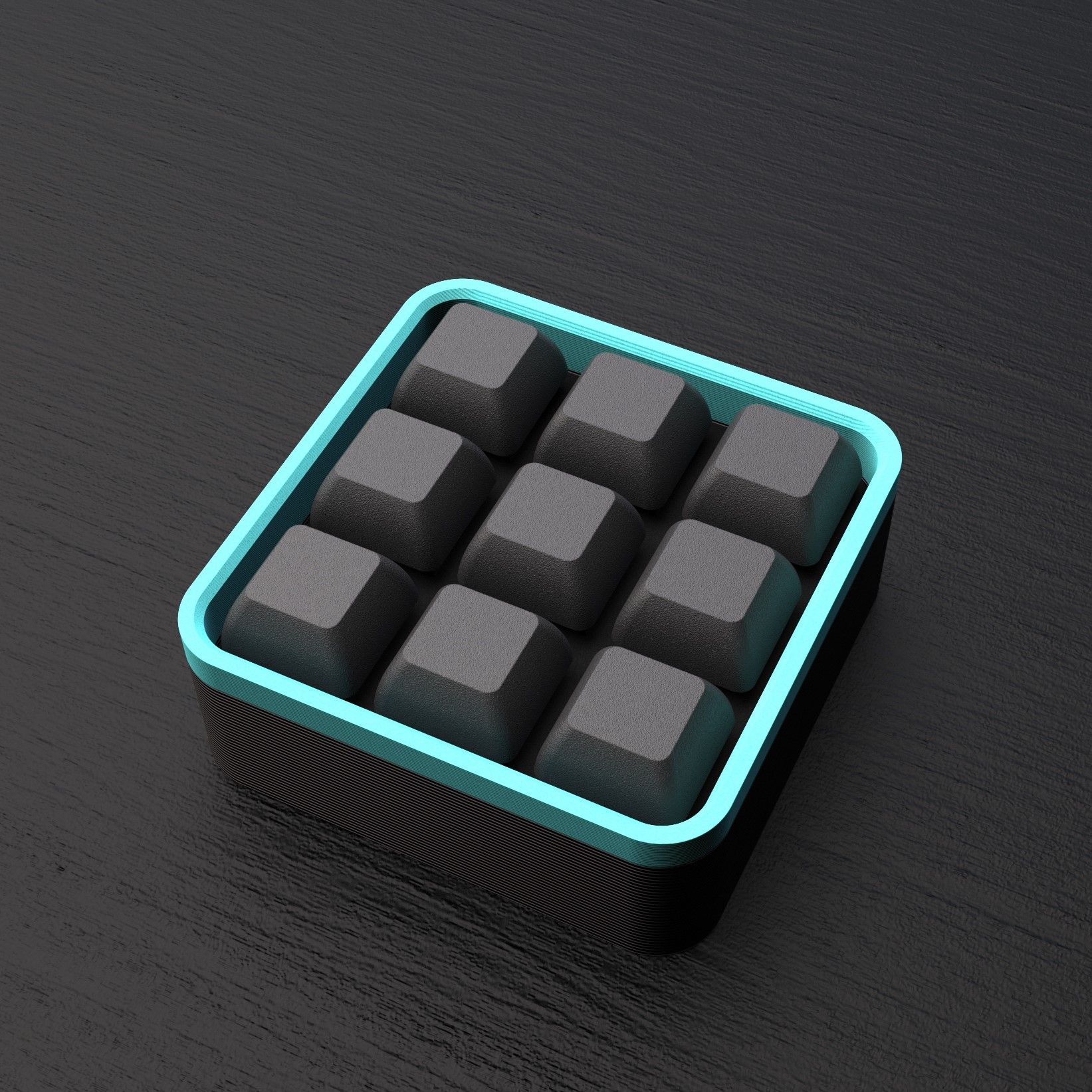
That also means it can be customized to different styles. I don’t have infinite filament at home, but I made a bunch of renders to see how it would look in different combinations of materials and colors.
Anyways, there’s a lot of room for improvement, and I’m planning to keep iterating on this.
Prototyping
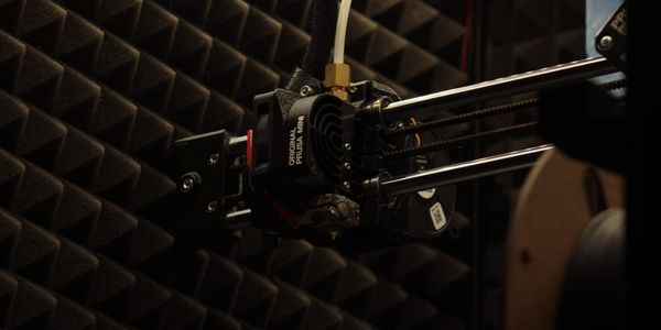
3D printing
Once I had the concept laid out, the first step was making a fit test for the switches. This way I could check the correct size for the slots before printing the whole plate and making the connections.
I checked the datasheet for the MX series provided by Sparkfun and measured the switches I had.
I decided to test with a 14 x 14 mm square slot, and do small adjustments from there.
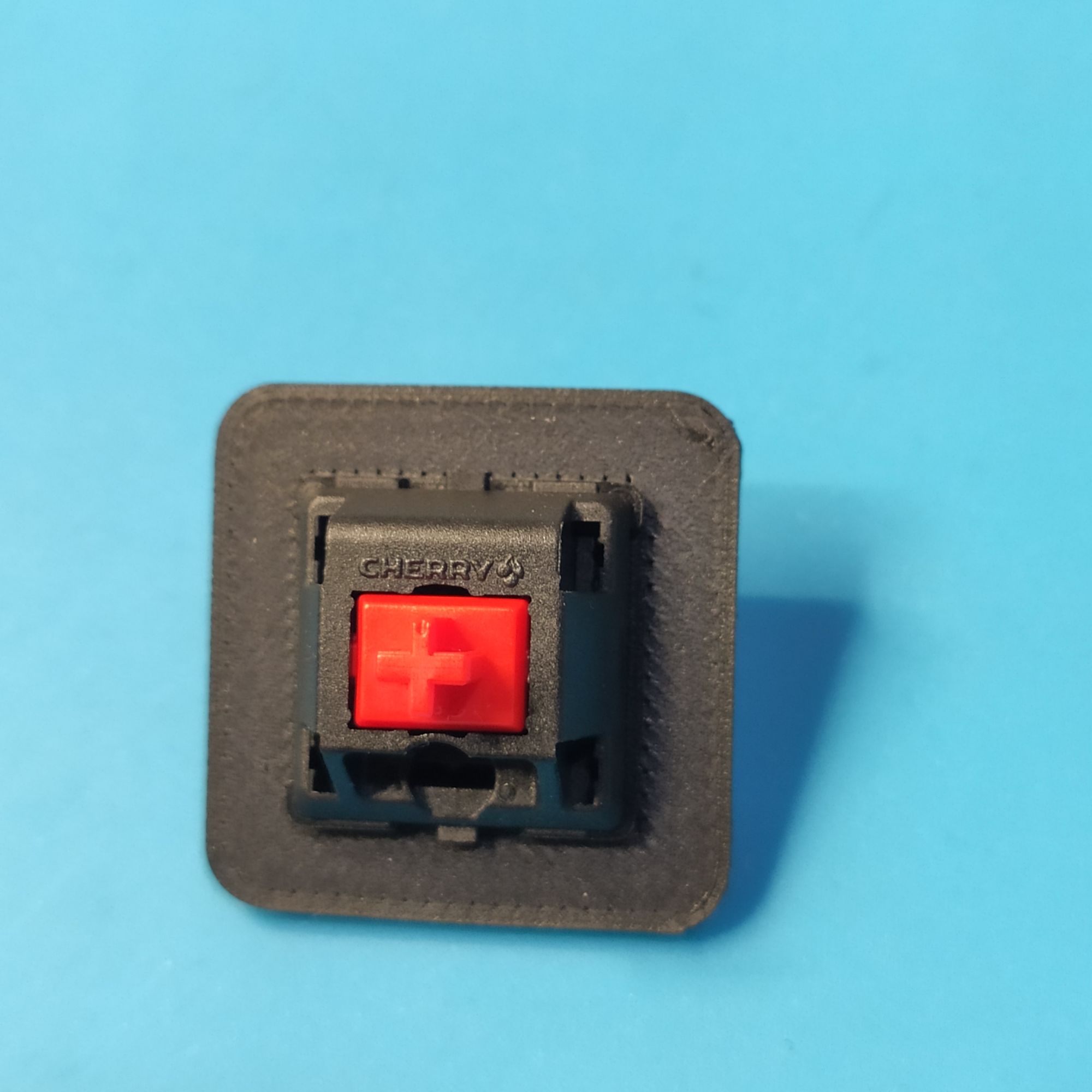
Luckily, it just worked on the first try, but it was worth testing. I'd recommend you do the same if you decide to build a 3D printed case too.
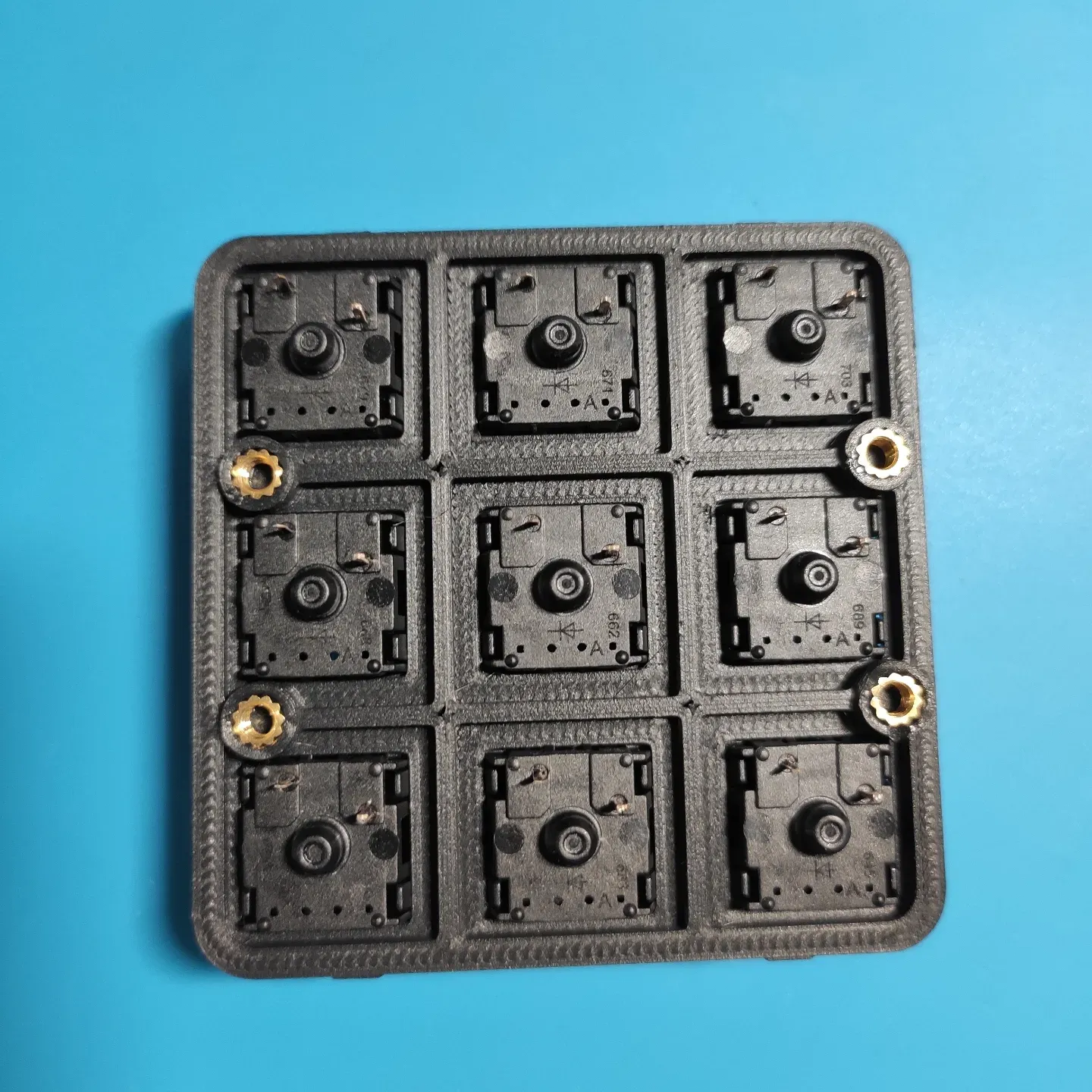
Knowing the correct size for the slots, I printed the switch plate and inserted the switches on it.
A simple plate with the switches in place was already a ton of fun and got distracted with it longer than I'm comfortable admitting before moving to the next step.
Wiring
There are two main options for wiring the switches to the Arduino Pro Micro - or to any other MCU or development board:
a) wiring each switch directly to a single pin and ground.
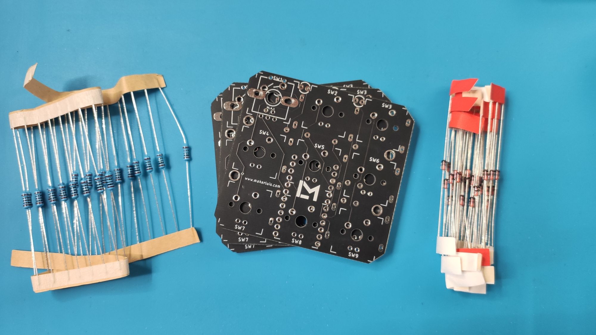
b) making a matrix of switches so that the microcontroller can index the pins by rows and columns with some coding. To do this, you need to add a diode to each switch, to avoid some weird things that happen when more than one key is pressed at a time. The advantage is that you need fewer pins from the micro, and fewer wires overall. Instead of 9 pins for 9 switches, you’d need only 6 pins (3 rows + 3 columns).
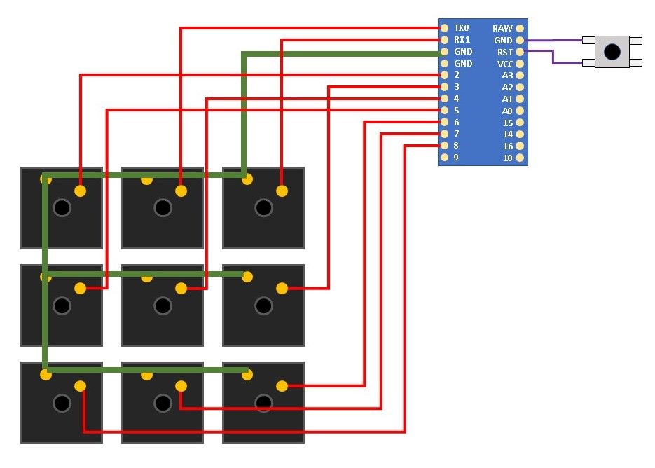
Since I didn’t have any diodes at hand, I made a hand-wired prototype with the switches connected directly to the pins of the Pro Micro and ground.
I tested the connections without soldering first, using some jumper wires and patience. I'm glad I did. You can see that by doing it this way things can get messy.
For the wires, you can use almost any gauge, ideally AWG 24 (0.5 mm section) or even smaller. There’s very little current flowing through these cables.
In my case, I had some leftover AWG 18 wires from an ATX power supply unit that I savaged last year. The larger the section of the wires, the more difficult the process of fitting everything in the enclosure.
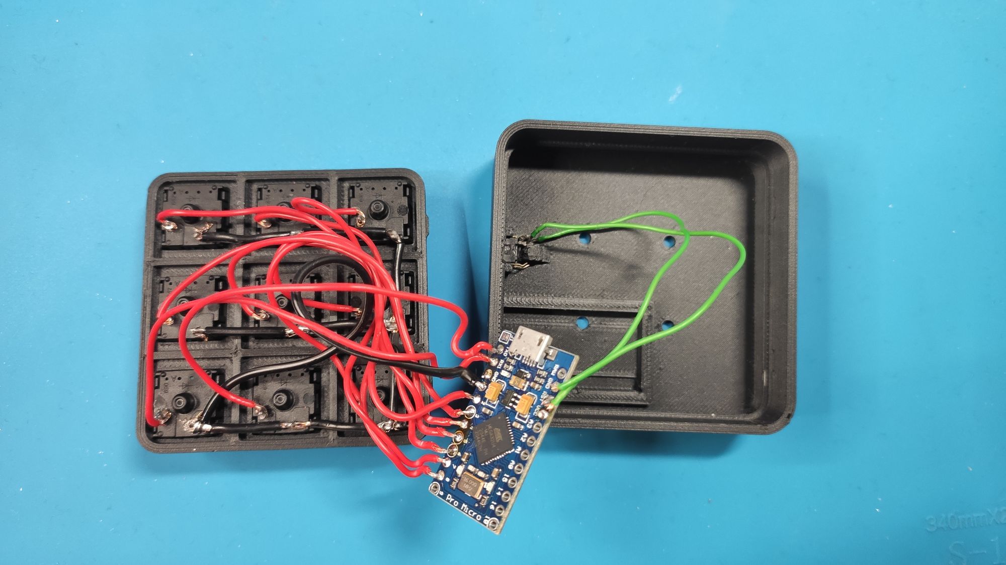
Something I forgot to add at first was a reset button for flashing the microcontroller. You just need a way to short the RST pin of the Pro Micro to GND, to put the ATMEGA32u4 in bootloader mode. Those are the green wires you see on the right side of the picture.
This is not needed in case you decide to work with firmware that allows you to reboot the board in bootloader mode. More on that later.
If you are interested in making your own hand-wired macro pad, you can check this great quality guide by Victor Lucachi.
Keyboard firmware
There are many options for programming a mechanical keyboard. I'm just telling you a bit about the ones I used, but you can find a more comprehensive description on the Wiki of r/MechanicalKeyboards.
Arduino
To test the circuit, I used a simple Arduino code.
There are pre-built libraries that allow you to make a keyboard very easily. Of course, you need to use a compatible board with native USB support, like the ProMicro, which is based on an ATMEGA32u4 microcontroller.
Using the examples from the library, you can configure basic functions on your keyboard. I learned from JohnMadLab that to use key modifiers like Ctrl presses, you can simply do the following inside your loop section:
/*Example code to do Ctrl+V with a single key press*/
if (digitalRead(KEY1) == LOW)
{ Keyboard.press(KEY_LEFT_CTRL);
	Keyboard.print("v"); delay(100);
}
if (digitalRead(KEY1) == HIGH) {
	Keyboard.releaseAll();
}
This type of code was great to test the wiring. But when I wanted to make more complex things I started to think I don’t have the time to learn, code and test all the functions I want out of a macro pad. So I started looking for alternatives.
It was at this point that I decided to learn more about the actual software used to develop keyboards. It seemed intimidating at first, but it isn’t that complicated.
QMK
QMK (Quantum Mechanical Keyboard) is the most widely used of the open-source frameworks out there. It allows you to control macros, RGB light effects, custom keycodes and includes something I knew I wanted but didn’t know how to call it: layers.
It is relatively easy to use, although you need a minimum level of comfort with code in case you want to customize it.
The official GitHub repository includes firmware files for hundreds of mechanical keyboard manufacturers, who make QMK-compatible keyboards.
Using QMK, you can embed complex functions in your keyboard or macro pad. This includes macros, and quantum features.
With those, you can even improve your workflow when developing your board, including debugging and maintenance/configuration tasks. For example, putting the micro controller in bootloader mode for flashing using a key (no need to short RST pin to GND with an external button!).
There are several resources I found to learn how to work with QMK. I think the most relevant ones in my case are:
- QMK official documentation
- Matteo Spinelli's Firmware guide
- Pascal Getreuer’s blog post about QMK triggers
Using Arduino Pins with QMK
When using firmware other than Arduino sketches, you’ll need to use the Pin names to match the ones of the microcontroller (AVR names). The names you see written on the board will not work outside of the Arduino framework. You can check the correct names in this article about the Pro Micro Pinout.
Also, most of the resources for using QMK are specific to switch matrix layouts. But I found that you can also use it for directly-wired pins considering mainly the following:
The only limitation I found when working with QMK was that it requires you to compile and flash new code to your board every time you want to make changes to the functions you programmed. This is inconvenient when you want to experiment with different features and don’t have the time to compile and flash repeatedly.
Here’s when I found out about VIAL, thanks to Jan Lunge’s video tutorials.
VIAL
VIAL (not to be confused with VIA!) is a fork of the official QMK repository. It provides a GUI that allows you to change the configuration of the macro pad (or keyboard) in real-time. That is, without compiling and re-flashing new firmware whenever you make a change to the configuration of the keys.
That is just awesome! The problem is, it is a hell of a lot more complicated to set up than QMK. Luckily, people out there provide great guides and video tutorials explaining what you need to do.
The configurations remain stored on the board, so when you plug it into another computer, it works as you expect.
There is a portable version, and even a web-based application, so you don’t need to install anything to your PC to configure the board, once you have flashed the firmware for the first time.
That’s exactly what I was looking for! With VIAL, I could edit my keys at work while I’m in a boring meeting for example.
What about wireless devices?
The only downside of VIAL (and QMK in general) is the lack of support for wireless devices, for example, the Bluetooth Low-Energy (BLE) that we see in commercial wireless keyboards. There are few documented expansion boards supported to add Bluetooth communication, but that requires using additional components to communicate via SPI with the AVR-based microcontroller. That would mean having the Atmega 32u4 (or the whole ProMicro) and this board from Adafruit, for example.
This is why my next step is to use ZMK. It is yet another type of firmware, with native support for BLE-compatible development boards.
Making a PCB
Once I figured out the connections, it was time for me to move on from hand-wired prototypes.
A macro pad is a simple application that makes a perfect test case for making your first PCB, in my opinion. There are only passive components and very small currents. Also, the signals being transferred are not so delicate. If it worked with a less-than-decent hand-wired circuit, it will work with a PCB, even if it is not optimal.
Since I was already working with Fusion 360 to create the enclosure, I decided to use Autodesk Eagle to design the PCB. I liked the possibility to synchronize the PCB designs between Eagle and Fusion 360. That made it easier to align all the components and make sure everything fit.
Where to start?
Starting from scratch is daunting, especially the first time.
At first, I was afraid of not knowing enough about PCB design and wasting time and money on something that didn’t work. However, this year I’ve decided to overcome this fear of failure, to accomplish more things, so I simply started.
I used a "for dummies" approach: learn the basics, then take an existing project and modify it. This way, I could see how others do things and learn from them.
I could also use some building blocks from other projects to speed up my design and complete the PCB quickly.
It's also important to know at least what you want to achieve with your PCB: define some minimum goals or requirements. So you don't get lost in the infinite possibilities out there and actually complete something.
Learning the basics
To learn the basics, in my case, meant learning how to use EDA software - in this case Eagle PCB. I was already familiar with the schematic diagrams, and the most intimidating part for me was making the actual PCBs.
I watched/listened two “getting started” tutorials on YouTube while doing chores at home, or on the train back from work.
The first one covered the basics of the user interface and how to get started with a new project. The video is quite long, so I skipped a few parts - I just wanted to refresh some things.
The second one, covered how to move from a schematic diagram to a PCB design, how to place the components, define the ground plane, create the traces, and so on.
I also learned how to create custom PCB silkscreens in Autodesk Eagle thanks to this tutorial by Adafruit.
Finally, after I received the boards, I found this great design guide for making keyboard PCBs. I will surely follow it for the next iteration of the design.
Don’t reinvent the wheel: start from existing designs
One great open-source macro pad project is the dumbpad which is really simple, has good documentation, and gave me an idea of what I wanted to include in the PCB. I actually copied some Eagle PCB blocks from the schematic files shared in their repository. However, I wanted the PCB to be square, with a small footprint, and avoid having the Arduino Pro Micro occupying horizontal space on my desk.
Luckily, the Pro Micro is wider than the Cherry MX switches, so I figured I could put the Arduino on one side of the board, and the switches on the other side.
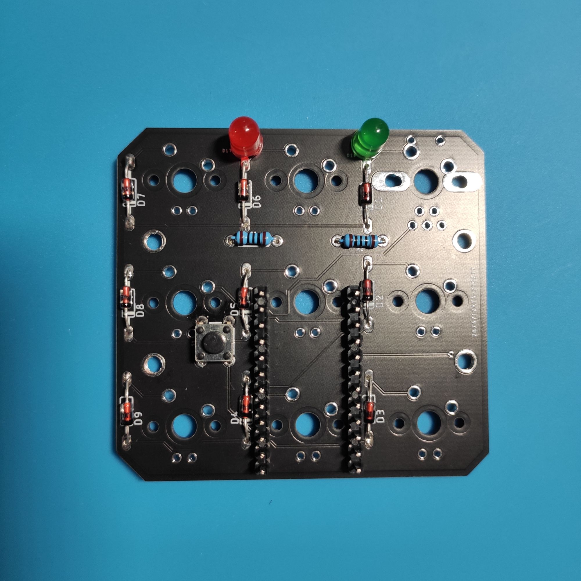
This meant that I’d need to be careful about the order in which I soldered the components. Something I forgot when I rushed to solder the first one.
Other than that, soldering the board and putting everything together was fun.
Set reasonable goals
This is a test board with simple features. It has no fancy RGB underglow or backlight. That's how it is supposed to be.
The only two LEDs I included are 6 mm in size, but they are meant for testing the direct control features of VIAL.
There’s also the footprint for an EC11 rotary encoder, to test how to use one of those for changing layers, controlling volume, zooming in/out, etc.
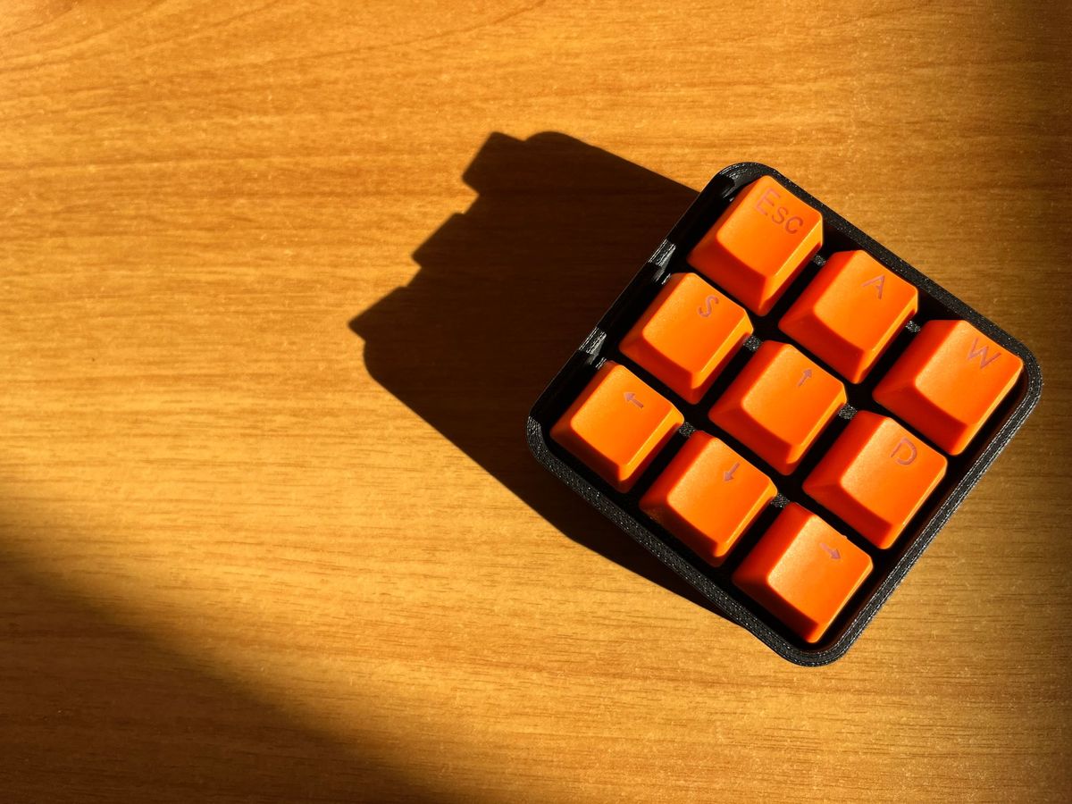
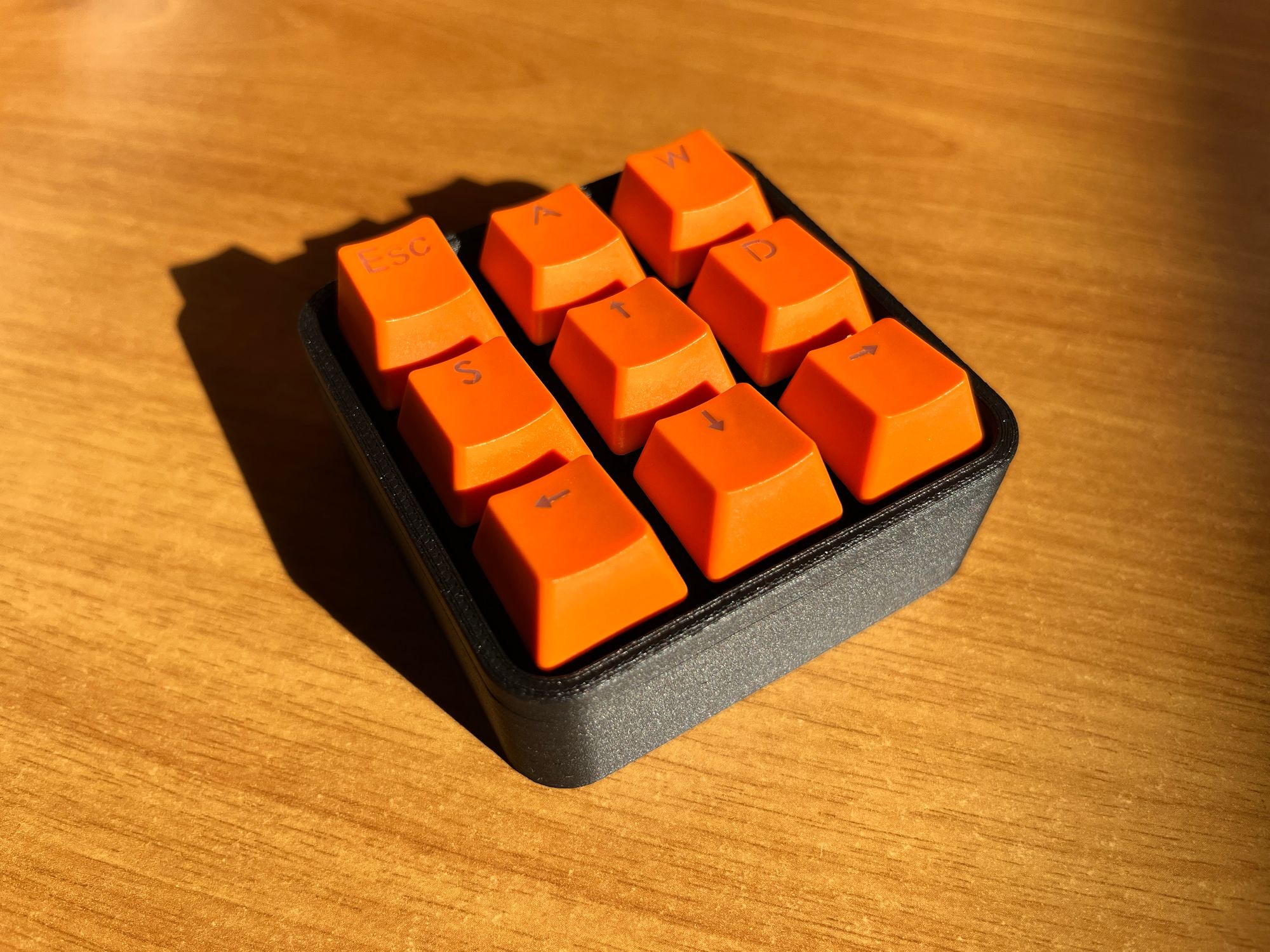
The finished prototype
Here’s what the finished prototype looks like. I don’t really like the orange, sculpted profile caps (I think they are Cherry type) but this is what I have at the moment.
Also, I’m glad I decided to use a ProMicro with Type-C USB port for the PCB version. It is much easier to use than the hand-wired version which used a micro-USB. And it also looks better :)
Using matte filament for the casing makes it look cleaner, in my opinion, compared to normal, glossier PLA.
Keycaps
Keycaps are an important feature of a macro pad. There are different types of profiles and sizes, and they affect both the look and feel of a keyboard.
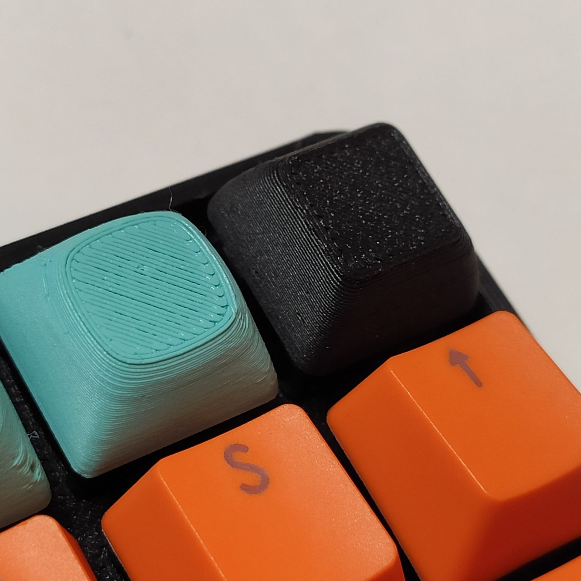
I ordered a few blank XDA profile keycaps from AliExpress to complete the first macro pads. In the meantime, I decided to print some to see how they looked.
Coincidentally, at the same time, there was a Flash Design Contest about 3D-Printable keycaps on Printables.com. So I uploaded the XDA keycaps design to the profile of TwoThingies.
Next Steps
In this first version, all the components are through-hole. I could make a version with SMT components to save more space and avoid having to use a whole ProMicro for the board.
I also regret not including RGB LEDs directly. I used the two LEDs to debug the code, but it would be very useful to have a proper indication of the current layer. With the current enclosure design, there are no openings for an RGB underglow effect, but I could make the bottom plate in transparent plastic to show the light of the RGB leds.
I’m also waiting for some EC11 encoders to arrive, to solder one of the PCBs and make a knob for image editing, zooming, volume adjusting, and so on.
Finally, I’ll try to order some CNC parts later on. I think having a hybrid 3d-printed case and anodized aluminum details would really make this design stand out.
Macro pads are cool, and now I have something else to spend time and money on - Not good! But I learned a bunch of things and had fun. Making my first PCB was great - especially because it worked - and now I’m looking forward to making many more, for different kinds of projects.
Thank you for reading this far!
I hope this post sparked some interest in this project and macro pads in general. I will write some updates as I progress on this, and share any useful things I discover in the process. If you'd like to follow along and get notified when I publish new content, consider subscribing to my blog.
Until next time,
Have a great day!