Step-by-step guide: design a macro pad on Fusion 360
I've prepared a step-by-step guide to help you create your own macro pad enclosure for 3D printing. This is also an easy project to learn more about Fusion 360.
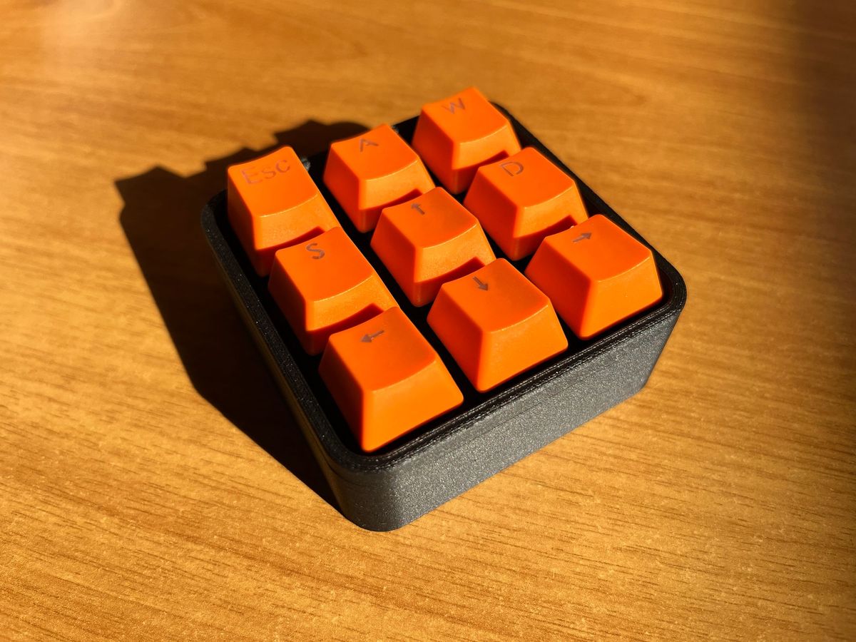
I've prepared this step-by-step guide to help you create your own macro pad enclosure for 3D printing. If you follow the exact dimensions I'm using, you'll end up with the first version of the enclosure design I shared in my blog post. But the idea is that you can modify it to make your own.
For this macro pad enclosure, you'll need the following components:
- Arduino Pro Micro
- Wire
- Soldering iron + solder
- 9 x Mechanical Switches (I used Cherry MX reds)
- 9 x Keycaps compatible with your switches
- USB cable
- 3D printed case
Optional:
- 9 x 1N4148 Diodes
- 1 x Momentary button (6 x 6 x 4 mm)
Contents
- Start with a single button
1.1 Create user parameters
1.2 Making a 1U switch plate - Complete the switch plate
2.1 Making a pattern
2.2 Add structure to the switch plate - Enclosure
3.1 Side walls
3.2 Switch plate support
3.3 Closing tabs - Bottom side
4.1 Base plate
4.2 Pro Micro slot - Optional features
5.1 Reset button
5.2 Opening holes - The finished design
- Additional resources
7.1 Hand-wiring the macro pad
1. Start with a single button
We will start by creating a switch plate to hold MX or similar mechanical switches. The first part will be a single "1U" module, that we will pattern to make the rest of the switch plate. Later on, you can 3D print this first module before prototyping the whole switch plate, to make sure the dimensions are correct for your 3D printer and filament.
1.1. Create user parameters
Click on "Change Parameters" on the top ribbon and create the following parameters:
switch_height = 14 mm
switch_width = 14 mm
switch_border_width = 3.5 mm
1.2. Making a 1U switch plate
We'll start by making a 1U plate to test the dimensions for the switches.
Create a new sketch on the XY plane. Draw a rectangle and dimension it using the switch_height and switch_width parameters we created before.
- Use the offset tool to make a copy of the center rectangle, and add
switch_border_widthas a dimension.
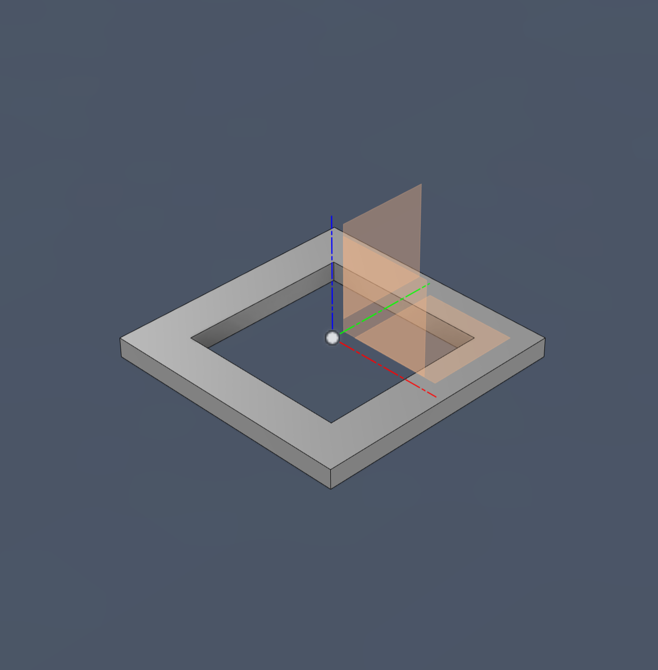
Click on the Extrude feature and extrude the profile we just created by 1.6 mm.
We've created a switch plate for a single mechanical switch. You can print this to test the fit of the switch plate before printing the rest of it.
Notes:
- I've extruded by -1.6 mm because I wanted to keep the top of the switch plate in the XY plane of the model. This is not necessary.
- You can add small chamfers (0.2 ~ 0.3 mm) to the inner edges if you are concerned about elephant foot effect on you print (your Slicer software may already have some compensation enabled)
Great! You can print this 1U plate and test the fit you get with the 3D printed part. You may need to change the size a little bit. To do so, you can just change switch_height and switch_width.
2. Complete the switch plate
We have just started. This 1U plate should give you an idea of what the workflow looks like. In reality, we are going to need a complete switch plate.
2.1. Making a pattern
Create two new user parameters:
rows_keysandcolumn_keys, both equal to 3 (no units!).- Edit
switch_border_width= 5.05 mm. - Create a sketch on the top face of the 1U plate.
- Draw a rectangle, with its bottom-left corner aligned with the bottom-left corner of the 1U plate. Make sure the lines have vertical and horizontal constraints.
- Add dimensions to the rectangle:
- the height will be equal to:
columns_keys * ( switch_height + switch_border_width ) + switch_border_width - the width:
rows_keys * ( switch_width + switch_border_width ) + switch_border_width
- the height will be equal to: