The power of Python and Fusion 360 for 3D printing
I'll show you how to create multiple versions of a Fusion 360 CAD model and export them as STL files for 3D printing, using a Python script.

Easily automate CAD file variations using Fusion 360's API
Hey everyone!
Today I want to share how I used a Python script to automate the process of creating multiple variations of a file for 3d printing. I wrote a script that uses the Autodesk Fusion 360 API to change the dimensions of a CAD model, and then exports each variation as an STL file that you can slice for 3d printing.
I was amazed by how simple it was to make this, so I wanted to share it with you. We'll be breaking down the code and explaining each section, so you can understand how it works and how you can use it for your own projects.
If you have any physical product idea that would require making changes to its geometry based on a series of parameters, you may certainly benefit from doing something like this. This case is really simple, since it includes only two parameters, and can be helpful to understand what’s needed.
Whether you're a young maker just starting out with 3D printing or an experienced designer looking to take your skills to the next level through automation, this post is for you.
Why exporting STL files automatically?
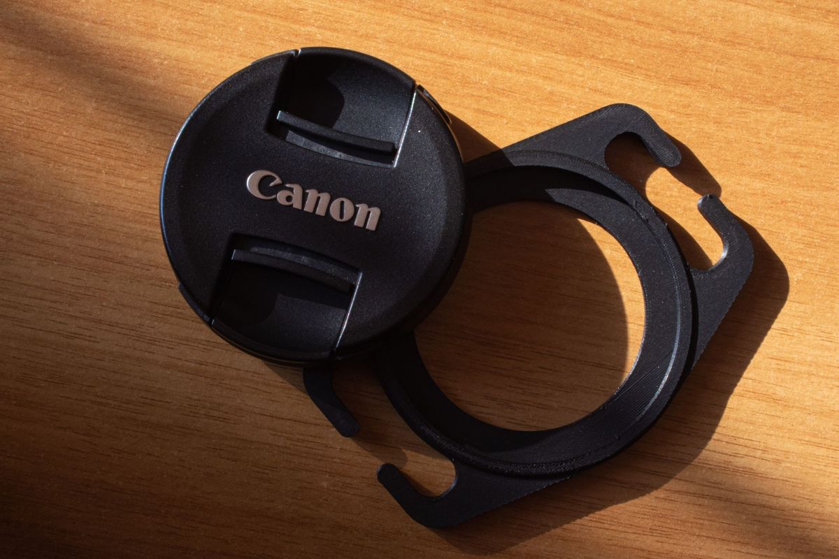
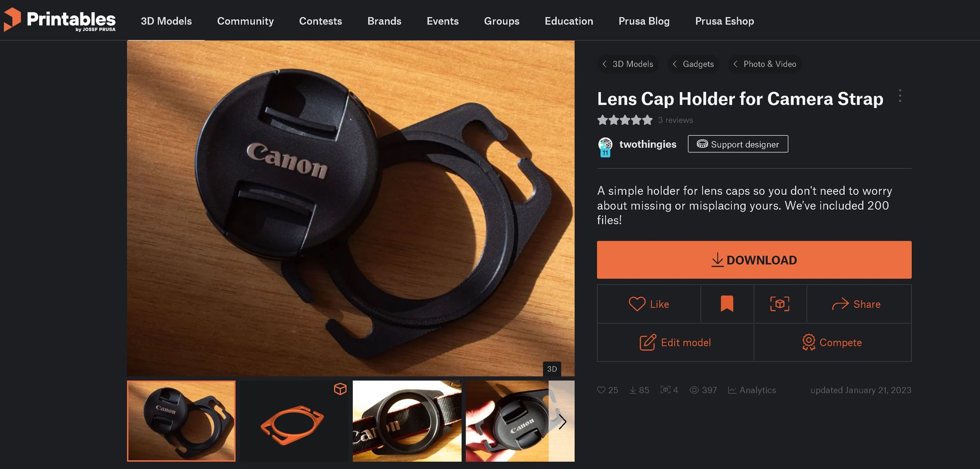
As you may know, TwoThingies is a project I started with Uri last year, and we have been sharing all sorts of useful files for 3d printing online. In this case, it was a design for a lens cap holder, which we shared on Printables.com, and recently included in the store on Vulkaza's marketplace.
Since we published the files online last year, we’ve regularly received requests from people who asked very nicely if we could make a design variation to fit a different size of lens or camera strap.
Initially, I would do the modifications and export the files manually, since the design was made on Fusion 360, and there were just two parameters to modify to get an adjusted version. But soon it started to become tedious, and I wanted to find a way to automate making several versions of the model and exporting them, see we could publish all possible sizes at once.
That became more important when we decided to open our store on Vulkaza, and include the Lens Cap holder as one of the listed designs. Ideally, anyone could go to the store and order a lens cap holder of any size.
Making a Parametric CAD model on Fusion 360
When I created the CAD file for this design, I knew there would be a point in the future when we would need to make variations of it.
So I designed it including some parameters and relationships that could be used for making changes, first by manually modifying their values, and later on through some kind of automation.
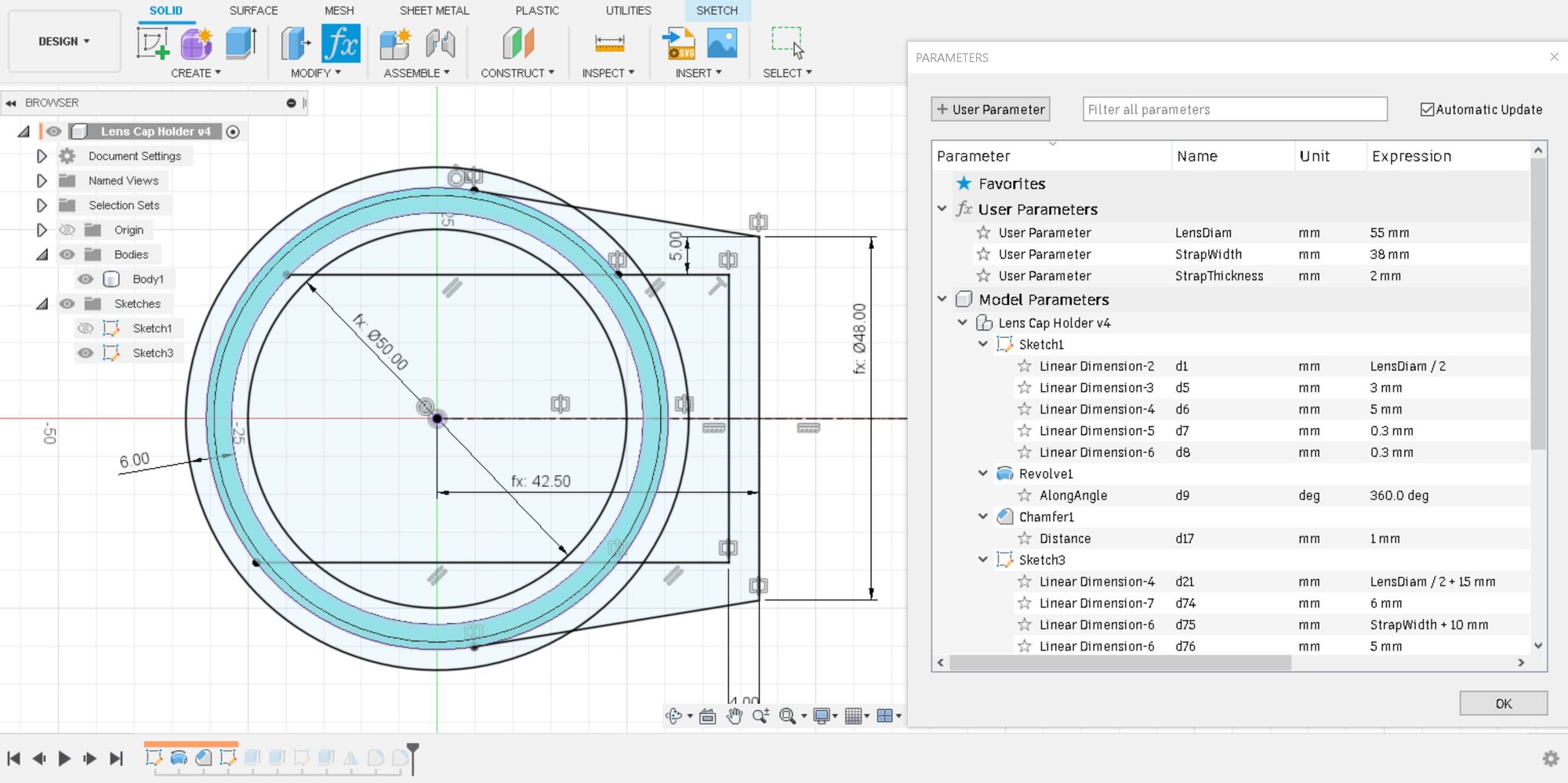
In this case, the two parameters I would use to change the size of the model were the diameter of the lens (LensDiam) and the width of the Camera Strap (StrapWidth). I also made a third parameter, for the thickness of the strap, which I ended up not using.
You can see in the image below the parameters and some of the formulas that reference back to them within the main sketch.
While doing some tests with the model, and trying different combinations of parameters, I had to remind myself of the most important rule for making parametric CAD models: do not leave un-constrained sketches in your design.
When you change the values of the parameters, everything can break with ugly results if there are sketch elements (a line, a point, an arc) with no constraints. That means every sketch entity must have either a dimension associated with it or a relationship (coincident, parallel, perpendicular, etc.) to another sketch entity.
The short, but very effective, rule of thumb is: there should be no blue lines on your sketch. In Fusion 360 blue lines represent un-constrained elements, that you can drag around with your mouse since they are not linked to anything, or at least they are not properly linked in all degrees of freedom.
the most important rule for making parametric CAD models: do not leave un-constrained sketches in your design.
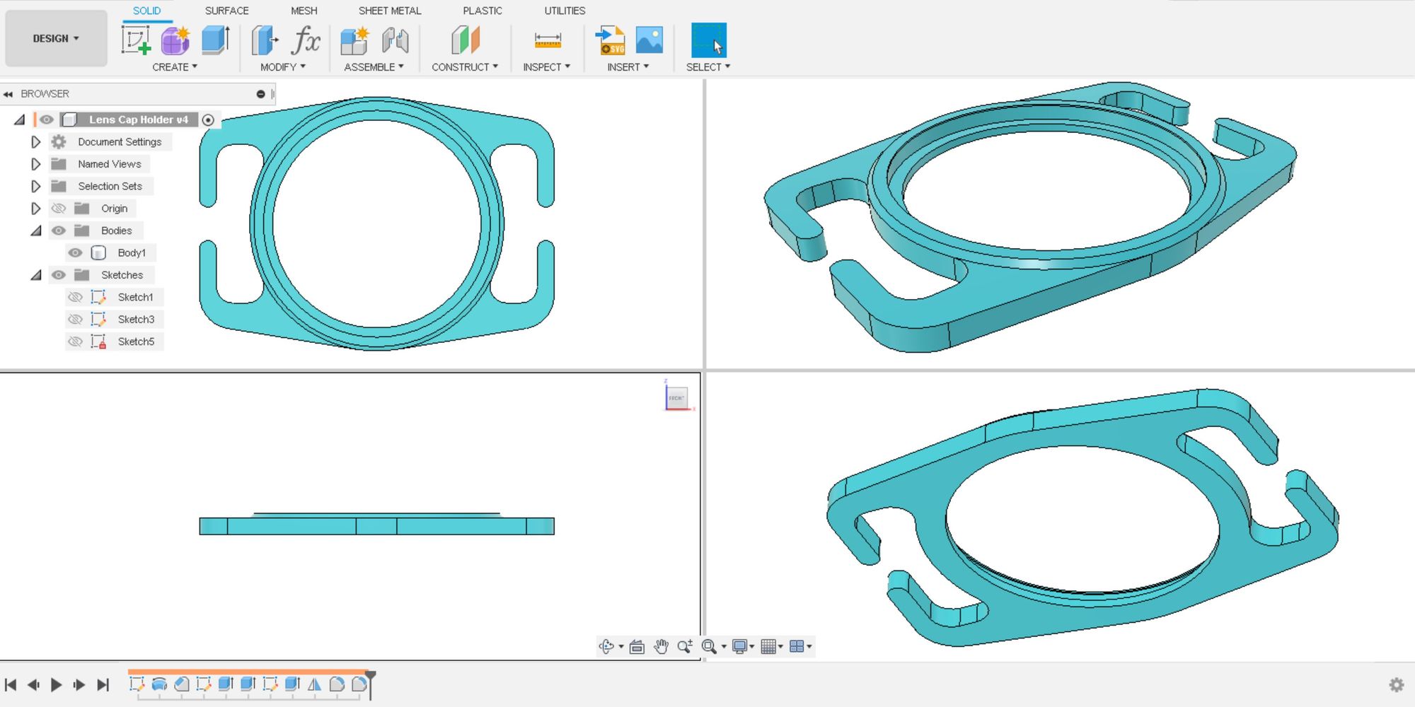
In this particular case, everything is linked to the lens diameter and strap width, which are the dimensions that will drive the changes to the geometry.
The different diameters of the holder are defined proportionally to LensDiam, except for some constant offsets that will be the same no matter the size of the lens, but their diameter is anyways defined as an offset from the lens diameter.
Also, the overall length of the holder will change based on the diameter, to avoid having too short or too long prongs for inserting the camera strap. The width of the sides, instead, is computed from StrapWidth.
Unlocking the Power of Automation: using the Fusion 360 API
I knew there was a Fusion 360 API that allowed making Python scripts for this kind of tasks, and this was the perfect opportunity to try it.
Not knowing where to start, my first obvious guess was to look into the official documentation. That allowed me to grasp the basics, especially about how to start creating a new script and start writing some code that Fusion 360 would recognize.
An especially useful resource was the Fusion 360 API Object model documentation. It includes a helpful graph showing how the different types of objects used by the API are related.
When automating things through the API, you’ll need to think in terms of the very basic steps needed to accomplish each task. Something that really helped me get these concepts clear in the beginning was this series of YouTube videos by Learn Everything About Design explaining how to use Fusion 360’s API, from the very basics of it.
How to start creating a new Python script for Fusion 360
The steps for starting a new script are actually very simple:
- Click on the Utilities tab in the top ribbon of Fusion 360.
- Click on Add-Ins. The Scripts and Add-Ins window will pop up. Click on the Create button.
- The Create New Script or Add-In window will show. You’ll be able to choose your preferred programming language (Python or C++), add a name and description for your script, author name, target operating system, and the folder where it will be saved.
- Once you fill that information, you can click Create. Your new script (for now, empty) will be added to the list on the Scripts and Add-Ins window.
- Now you can select it and click Edit and a new instance of Visual Studio Code will open, with a pre-loaded file containing a template for you to start writing your new script. It will ask you whether you trust the authors of the files before you can access them. Click yes, and you’ll be ready to go.
Writing a Python script to update CAD model parameters
This is when the fun part starts.
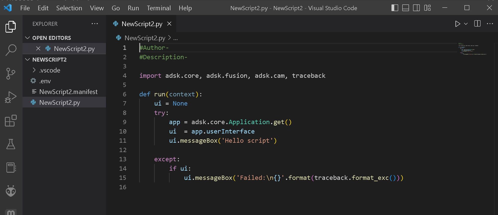
As you can see, the template script already tells you some libraries you’ll need: 'adsk.core', 'adsk.fusion', and 'adsk.cam'. These modules provide access to the Fusion 360 API and allow the script to interact with the active design. The rest is just about using the right Classes of objects and the right methods to interact with Fusion 360, for each little task you need to do for completing a larger task.
In my case, I needed to get access to the User-defined parameters, modify them, wait for the design to be updated, and export it as an STL file. I would need to do this recursively, for different combinations of LensDiam and StrapWidth.
I knew there would be already some code to do something similar to what I wanted to accomplish, so once I understood more clearly what I needed to do, I started looking for some examples to start from. Luckily, I found this code from Brian Ekins, answering a question in the Fusion 360 Community forum, from about 6 years ago.
I just needed to modify it slightly, and came up with the following one:
#Luis Medina -
# Update the diameter of Lens Cap Holder and save each version as STL

import adsk.core, adsk.fusion, adsk.cam, traceback

def run(context):
    ui = None
    try:
        app = adsk.core.Application.get()
        ui = app.userInterface
        design = adsk.fusion.Design.cast(app.activeProduct)

        defaultInputMinDiam = '35'
        minLensDiam_Input = ui.inputBox('Input diameter in mm: ',
                                'Define minimum diameter', defaultInputMinDiam)

        defaultInputMaxDiam = '80'
        maxLensDiam_Input = ui.inputBox('Input diameter in mm: ',
                                'Define maximum diameter', defaultInputMaxDiam)

        defaultInputWidth = '35'
        StrapWidth_Input = ui.inputBox('Input width in mm: ',
                                'Define strap width', defaultInputWidth)
        ui.messageBox(f'Input is = {StrapWidth_Input[0]}')

        defaultInputFolder = r'C:\\\\'
        folderInput = ui.inputBox('Input path to save folder: ',
        'Define Save Folder', defaultInputFolder)

        folder = folderInput[0]

        diameters = list(range(int(minLensDiam_Input[0])-1,int(maxLensDiam_Input[0])+1,1))

        # Get the root component of the active design
        rootComp = design.rootComponent

        # Get the parameters named "Length" and "Width" to change.
        LensDiam_par = design.allParameters.itemByName('LensDiam')
        StrapWidth_par = design.allParameters.itemByName('StrapWidth')

        for dim in diameters:

            Diam_set = dim
            Width_set = StrapWidth_Input[0]
            LensDiam_par.expression = str(Diam_set)
            StrapWidth_par.expression = str(Width_set)

            # Let the view have a chance to paint just so you can watch the progress.
            adsk.doEvents()

            # Construct the output filename.
            filename = f'{folder}\\LensCapHolder_D{Diam_set}mm_Strap_{Width_set}mm.stl'

            # Save the file as STL.
            exportMgr = adsk.fusion.ExportManager.cast(design.exportManager)
            stlOptions = exportMgr.createSTLExportOptions(rootComp)
            stlOptions.meshRefinement = adsk.fusion.MeshRefinementSettings.MeshRefinementMedium
            stlOptions.filename = filename
            exportMgr.execute(stlOptions)

        ui.messageBox('Finished.')
    except:
        if ui:
            ui.messageBox('Failed:\\n{}'.format(traceback.format_exc()))
Let’s break it down into what each section of the code is doing.
The Python code, explained
The script starts by importing the necessary modules for accessing the Fusion 360 API, as well as the itertools module, which we will use later to generate a list of diameter combinations.
import adsk.core, adsk.fusion, adsk.cam, traceback
Then, we define a run function, which will be executed when the script is run. The function starts by initializing the Fusion 360 API and getting a reference to the active design.
def run(context):
    ui = None
    try:
        app = adsk.core.Application.get()
        ui = app.userInterface
        design = adsk.fusion.Design.cast(app.activeProduct)
Next, the script prompts the user to input the minimum and maximum diameter of the lens cap holder, and the width of the strap, using the inputBox method of the user interface. This is used to make all possible values between the minimum and maximum diameter, with the opening for the camera strap width provided.
I wanted to have this possibility, to avoid coding all the rules to avoid wrong results due to incompatible combinations of lens diameters and strap width. The CAD model only works for strap widths equal or larger than the lens diameter, but I didn’t code errors and exceptions to account for that. Maybe later.
defaultInputMinDiam = '35'
minLensDiam_Input = ui.inputBox('Input diameter in mm: ',
                                'Define minimum diameter', defaultInputMinDiam)

defaultInputMaxDiam = '80'
maxLensDiam_Input = ui.inputBox('Input diameter in mm: ',
                                'Define maximum diameter', defaultInputMaxDiam)

defaultInputWidth = '35'
StrapWidth_Input = ui.inputBox('Input width in mm: ',
                                'Define strap width', defaultInputWidth)
The script also prompts the user to input the path to the folder where the STL files will be saved.
defaultInputFolder = r'C:\\\\'
folderInput = ui.inputBox('Input path to save folder: ',
        'Define Save Folder', defaultInputFolder)

folder = folderInput[0]
Then, we create a list of diameters to iterate over, based on the minimum and maximum values provided by the user. I used range, and gave an offset of 1 mm to the values, to include the in the list of diameters.
diameters = list(range(int(minLensDiam_Input[0])-1,int(maxLensDiam_Input[0])+1,1))
Next, we get a reference to the root component of the active design, and the parameters that we want to change, in this case the lens diameter and the strap width.
rootComp = design.rootComponent
LensDiam_par = design.allParameters.itemByName
StrapWidth_par = design.allParameters.itemByName('StrapWidth')
Finally, we can iterate over the list of diameters to change the parameters and export the geometry as STL files:
for dim in diameters:

            Diam_set = dim
            Width_set = StrapWidth_Input[0]
            LensDiam_par.expression = str(Diam_set)
            StrapWidth_par.expression = str(Width_set)

            # Let the view have a chance to paint just so you can watch the progress.
            adsk.doEvents()

            # Construct the output filename.
            filename = f'{folder}\\LensCapHolder_D{Diam_set}mm_Strap_{Width_set}mm.stl'

            # Save the file as STL.
            exportMgr = adsk.fusion.ExportManager.cast(design.exportManager)
            stlOptions = exportMgr.createSTLExportOptions(rootComp)
            stlOptions.meshRefinement = adsk.fusion.MeshRefinementSettings.MeshRefinementMedium
            stlOptions.filename = filename
            exportMgr.execute(stlOptions)
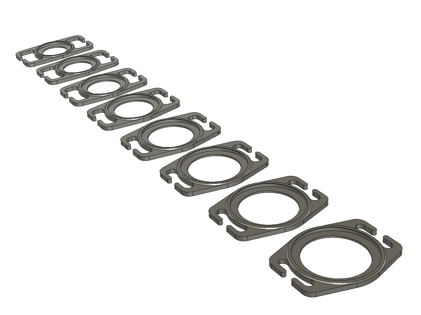
I ran the script a few times, for camera strap widths of 35, 38, 40, 45 and 50 mm. Each time the minimum diameter was equal or bigger than the strap width. That is how I obtained the 200 files we published on Printables.com.
Conclusion
In conclusion, using the Fusion 360 API, we can make relatively simple scripts to automate the creation of different versions of a file and export each one in STL format, ready for slicing and 3D printing.
By using this kind of scripts, you can save time and effort by generating a batch of similar models with different dimensions, all at once - of course, you first need to make a parametric CAD model compatible with this kind of automation.
I hope this post has been helpful in explaining how the script I made works and how you can use it to automate your own 3D printing projects. The script and the Fusion 360 file are available on my Github, and you are welcome to fork them and use them to create your own projects.
Uri and I will also be working on a version of the lens cap holder that will allow fitting two different diameters instead of one, so stay tuned for that - we will publish it, as usual on the Instagram account of TwoThingies.
As a friendly reminder, always check the dimensions of your camera lens caps and strap to ensure compatibility before 3D printing any of the files we shared!
Happy automating and printing!