3 keyboard macros to speed up your Simulink workflow
I configured my macro pad to improve the way I use Simulink. See how you can use custom shortcuts to save time.


Recently, I’ve been trying to find new ways to improve my productivity by cutting up the time it takes me to do repetitive actions.
I have noticed the three most repetitive actions I do while working on Matlab Simulink for Model-Based software development and found a way to do them semi-automatically, using keyboard macros that I configured on the custom macro pad that I made.
If you work with Simulink, you'll love to see how much time you can save using macros. Let me show you how I did it.
Recording of the 3 macros I made. This video is not speed-up. I recorded it on my personal computer, which is not as fast as the workstation I use at work. This is why there’s such a delay from macro activation to result. Still, it is faster than doing these things manually.
Model-Based software design using Simulink
As I mentioned before, the shortcuts I’m about to show are specific to Simulink. They are especially useful if you do Model-Based Design (MBD) software development, which is commonly used in the automotive industry.
The three most common tasks I find myself doing while working on Simulink are:
- Batch aligning blocks
- Batch distributing blocks
- Batch adding matching blocks and connecting them
Simulink does offer some buttons and shortcuts for doing these operations, but you still need to navigate a few menus to access them. There’s also the possibility to create scripts to automatically create models based on some rules, but that’s something you would only use for specific cases, while the rest of the work is most likely done manually.
After looking for keyboard shortcuts for Simulink, I was not satisfied with the results and decided to use my macro pad to implement a few macros that help me do these things easily.
Shortcut for aligning blocks on Simulink (with a single key press)
The ALIGN commands in Simulink are located in the FORMAT tab of the Toolstrip. They are only available when you select multiple blocks.
The normal way you’d use would be by selecting the target blocks, clicking on the FORMAT tab, and then selecting the type of alignment you need.
One way to do this more quickly is by adding the align commands to the Quick Access Toolbar. You can do this by right-clicking on any icon of the Toolstrip as you can see below.
Adding the Align Center command to the Quick Access Toolbar
However, I wanted to do this by pressing a button instead, using a macro. So I needed to access these commands using the keyboard.
That’s when I discovered that you can press Ctrl+Period (.) to access the actions search menu. From there, you can search for many commands, including the ones for aligning blocks.
How to access the Action Search menu by pressing Ctrl + (.)
That’s just what I needed.
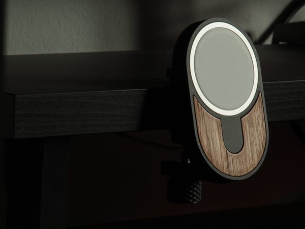
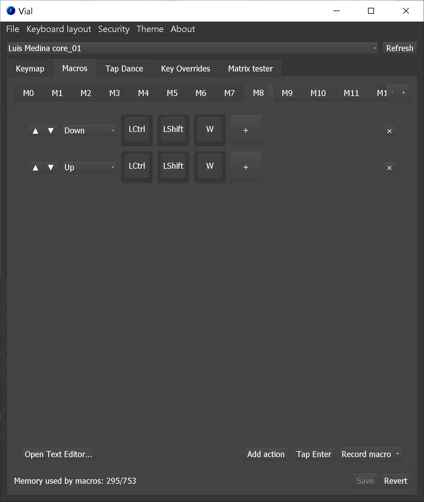
Using VIAL, I created the following macro, so I can run the align commands with a single button press. I added macros for left, right and center alignment, and assigned them to the top three keys of my macro pad, so they’re easy to remember.
This is the first macro you see me using in the video at the beginning of the post. I just press one button all the selected blocks get aligned.
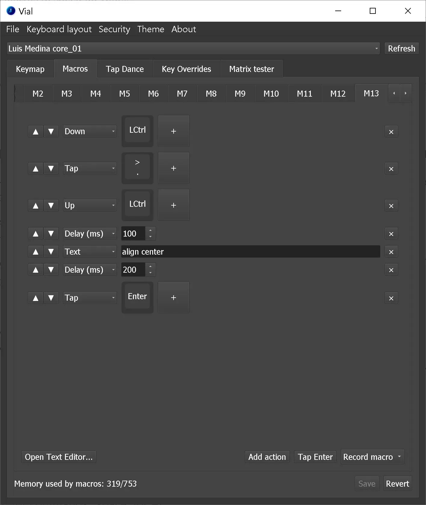
Batch distributing blocks vertically
To distribute blocks vertically using a single key press, I did a similar thing. I created a macro to press Ctrl + Period(.), wait a few milliseconds, and type in the command I need. In this case, I just wrote “vertically” to reduce the time it takes the macro to complete. This is what the macro looks like:
Creating multiple matching blocks at once
This one is the most powerful one out of the three macros I'm sharing with this post. For me, it's a huge time saver.
Using this macro, I can create multiple matching blocks for a selection. The best part is, it supports creating different types of blocks, depending on the selected items.
You can see how it works in the video at the beginning of this article. Using the same button, I can make matching Goto, From or Outport blocks, for just the selected items.
Let me tell you how I did it.
First, I created a script that allows me to access the currently-selected system, and get the handles of the selected blocks. Then, the script loops through the handles and creates matching “From” blocks automatically.
subsystem = gcs;
goto_objects =  Simulink.findBlocksOfType(selection, 'Goto', 'Selected', 'on');

for i_block = 1:numel(goto_objects)
    tag = get_param(goto_objects(i_block), 'Gototag');
    origin_position = get_param(goto_objects(i_block), 'Position');
    dest_block = [subsystem '/Goto'];
    dest_position = origin_position + [200 0 200 0];
    handle = add_block('built-in/from', dest_block, 'MakeNameUnique','on');
    set_param(handle, 'Gototag', tag, 'Position', dest_position);
    open_system(subsystem );
end
% save as batchgoto.m
% add to MATLAB Path
This worked great, but I knew I could generalize it. When doing this type of operation, I'd often find myself in the following scenarios:
- I have multiple Goto blocks from which I want to add the matching From blocks (the case I just solved using the script above)
- There are multiple input ports from which I want to add Goto blocks.
- I need to add output ports matching several From blocks.
Regardless of the case, I often want the lines to be named as the name of the output ports or the Goto tags being used. Naming the lines is needed if you want to log the signals - for example, on INCA - assuming the signal name has been added to the data dictionary referenced by your model for code generation. If you don't need to log them, having named lines doesn't hurt in most cases.
The script I came up with determines the type of each selected block and creates the matching one based on the three scenarios I mentioned above.
The corresponding blocks are placed vertically aligned with the original selection of blocks, and the lines are named automatically using the Goto tags or port names, depending on the case.
This is what the script looks like:
subsystem = gcs; % Get current system
objects =  gsb; % Get selected blocks
% Alternative: find_system(gcs,'Selected','on')

for i_block = 1:numel(objects)

    % Add Outports and connected lines for From blocks
    if strcmp(get_param(objects{i_block}, 'BlockType'), 'From')
        % Get the tag and position of the From block
        tag = get_param(objects{i_block}, 'Gototag');
        origin_position = get_param(objects{i_block}, 'Position');

        % Define the destination of the new block
        dest_block = [subsystem '/' tag];
        y_line = origin_position(2) + (origin_position(4) - origin_position(2))/2;
        dest_position = [origin_position(1) + 200 ...
                         y_line - 7 ...
                         origin_position(1) + 230 ...
                         y_line + 7 ];
        % Add the new block and get its handle, then position it
        dest_handle = add_block('built-in/Outport', dest_block, 'MakeNameUnique','on');
        set_param(dest_handle, 'Position', dest_position);

        % Add connecting line
        OriginPortHandles = get_param(objects{i_block},'PortHandles');
        DestPortHandles = get_param(dest_handle,'PortHandles');
        line_handle = add_line(subsystem,OriginPortHandles.Outport(1),...
                                DestPortHandles.Inport(1));
        set_param(line_handle, 'Name', tag)
    end

    % Add Gotos and connected lines for Input blocks
    if strcmp(get_param(objects{i_block}, 'BlockType'), 'Inport')
        % Get the tag and position of the Inpot block
        name = get_param(objects{i_block}, 'Name');
        origin_position = get_param(objects{i_block}, 'Position');

        % Define the destination of the new block
        dest_block = [subsystem '/Goto'];
        y_line = origin_position(2) + (origin_position(4) - origin_position(2))/2;
        dest_position = [origin_position(1) + 150 ...
                         y_line - 7 ...
                         origin_position(1) + 300 ...
                         y_line + 7 ];

        % Add the new block and get its handle, then name it
        dest_handle = add_block('built-in/Goto', dest_block, 'MakeNameUnique','on');
        set_param(dest_handle, 'Gototag', name, 'Position', dest_position);

        % Add connecting line
        OriginPortHandles = get_param(objects{i_block},'PortHandles');
        DestPortHandles = get_param(dest_handle,'PortHandles');
        line_handle = add_line(subsystem,OriginPortHandles.Outport(1),...
                                DestPortHandles.Inport(1));
        set_param(line_handle, 'Name', name)
    end

    % Add Froms for Goto blocks
    if strcmp(get_param(objects{i_block}, 'BlockType'), 'Goto')
        tag = get_param(objects{i_block}, 'Gototag');
        origin_position = get_param(objects{i_block}, 'Position');
        dest_block = [subsystem '/Goto'];
        dest_position = origin_position + [200 0 200 0];
        handle = add_block('built-in/from', dest_block, 'MakeNameUnique','on');
        set_param(handle, 'Gototag', tag, 'Position', dest_position);
    end

	% Return focus to the target subsystem (return to Simulink)
    open_system(subsystem);
end
% Save as addblocks.m
% add to MATLAB Path
To run this code using a macro, I saved it as addblocks.m and added the folder to the MATLAB path.
Creating actual custom commands in Simulink
I wanted to be able to run this script by pressing a single button.
Fortunately, I found this old blog post by Guy Rouleau where he explained how to create actual custom shortcuts in Simulink.
To create a custom Simulink command for my script, I just needed to use the following code:
function sl_customization(cm)
    cm.addCustomMenuFcn('Simulink:ToolsMenu', @getMyMenuItems);
end


function schemaFcns = getMyMenuItems(~)
    schemaFcns = {@autoAddBlocks};
end

function schema = autoAddBlocks(~)
    schema = sl_action_schema;
    schema.label = 'Batch Add Blocks';
    schema.statustip = 'Batch Add Blocks';
    schema.accelerator = 'Ctrl+Shift+w';
    schema.callback = @autoAddBlocksCS;
end


function autoAddBlocksCS (~)
    addblocks
end
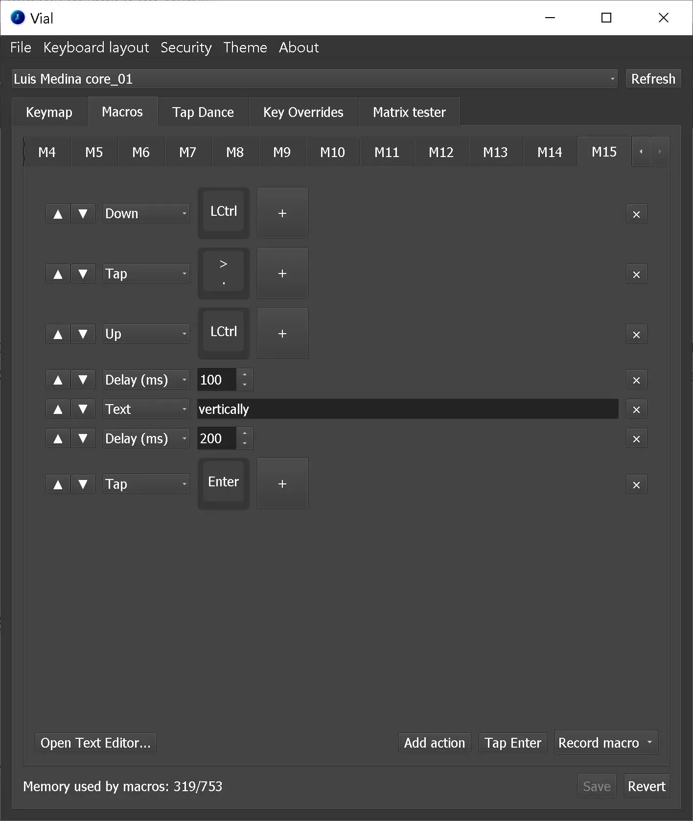
By saving this file in my Matlab path as sl_customization.m, and running sl_refresh_customizations from the command window, I get a new command on the Simulink Tools menu called Batch Add Blocks.
Thanks to this, I can simply configure my macro pad to press Ctrl + Shift + w in order to call the addblocks function I made. The final macro on VIAL is shown below.
How to implement custom macros and shortcuts on your computer?
There are different ways to configure custom macros on your computer. In general, they’ll require you to either:
- install additional software that you can use to configure the macros on your existing keyboard and mouse
- or use an additional input device with more buttons to which you can assign the macros - you’ll also need the software required to configure the device.
Windows users can purchase a Microsoft mouse or keyboard, and assign macros to them using Microsoft’s mouse and keyboard center. This only works for supported devices.
Another option is to use AutoHotKey to create custom macros or even scripts, and assign them to some key combinations. This option is really powerful, and you can use it to build complex macros robustly. AutoHotKey is an open-source software, with a wide community of users. They have official documentation, and you can also find tutorials and community guides on their user's forum, the dedicated subreddit r/AutoHotkey, and even a Discord channel.
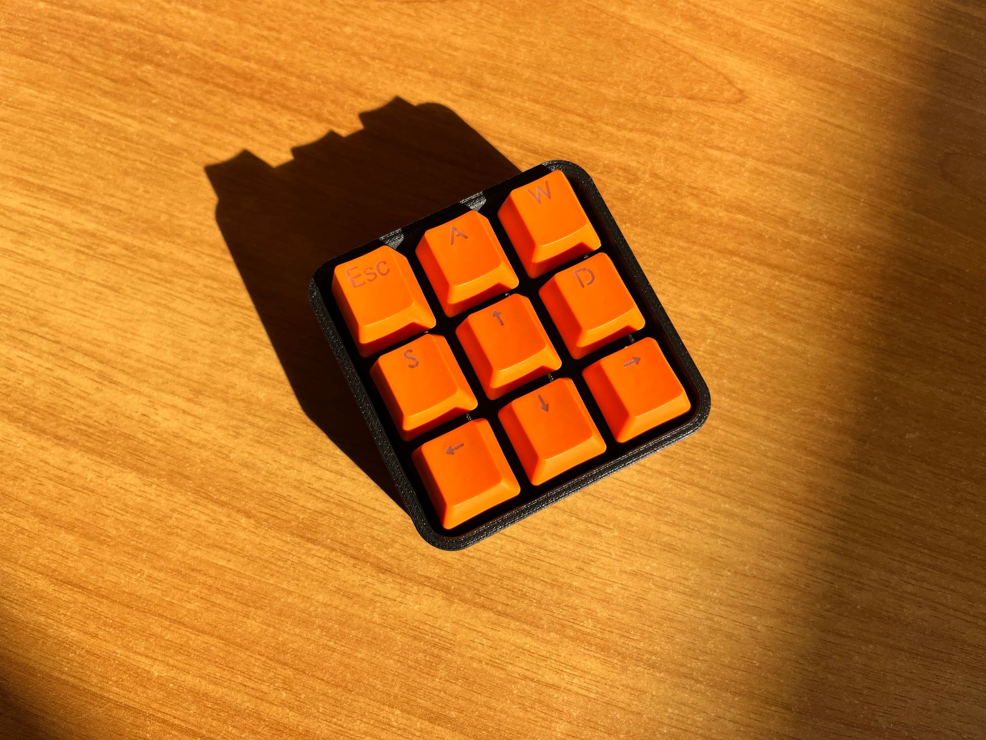
The third option is the one I preferred: you can buy or make a configurable macro-pad. I like this option because this allows you to have dedicated keys for your macro, so you don’t have to remember complicated key combinations in your existing keyboard. If your keyboard is compatible with GUI-based configuration tools, it is really easy to implement keyboard shortcuts and macros, without having to write scripts.
I like making stuff, so I made my own VIAL-compatible macro pad.
Both my primary personal computer and the one I use for work are based on Windows, so I haven’t tested any methods for Linux or MacOS, although using a configurable macro pad should work without problems in those operating systems too (for MacOS the macros would need to be changed from ‘Ctrl’ to ‘Cmd’).
Conclusion
While these macros will not make your Simulink model better, at least you'll save some time and avoid procrastinating because you don't want to re-factor that whole ASW function you made just because it'll require you to manually add hundreds of blocks and lines in different places and you don't want to make a script to do it because every time will be different.
I'm not a fan of Simulink and AUTOSAR-compliant code. I just use it in my day job and doing this was simply a way for me to improve my Simulink experience. I might post other useful macros for things like CAD modeling, coding in Visual Studio Code, or working with Jupyter Notebooks.
If you enjoyed this post, subscribe to my newsletter to receive updates on new projects I'm working on.
Happy Easter!